3D Printing PCB Prototypes
Most of the PCBs I have been designing are add-ons for existing boards. This requires precise measurements to ensure components and mounting holes are in exact locations. This is the method I have come up with for creating prototype PCBs to ensure fit and compatibility. This is only for fit and sizing and not for circuit testing.
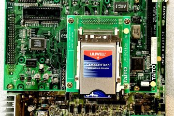
Today I am working on a stereo audio PCB add-on for the Seibu SPI. The stereo PCB will mount to existing holes on the Seibu’s audio heat sink. There will be 2 capacitors on this board which I would like to mount on the bottom of the PCB. I need to make sure the mounting holes line up, the board edges match, and that the capacitors will fit properly in the location I chose.
Tools: Autdesk Eagle Free, Adobe Illustrator, and TinkerCAD
PCB Design Export
- Open the completed PCB board design in Eagle
- Click the Manufacturing tab on the right side of the screen.
- On the Preview tab, select the Drills layer and click Export Image.
- Save the image as a PNG file.
- Select the Board tab, expand the Board information section, write down the length and width measurements of your design. You will need these measurements when we resize the PCB in TinkerCAD.
Converting to SVG
- Open the PNG file in Adobe Illustrator
Highlight the PCB object.
Click the down arrow next to Image Trace, select 3 Colors, click OK at the warning window if prompted.
After the trace completes highlight the image again and click Expand.
Double click the PCB image to expand the object group, then single click the PCB outline to highlight it.
Hit CTRL+X on the keyboard to cut the PCB outline.
Hit CTRL+A to highlight all parts and hit DELETE on the keyboard to delete the excess object parts.
Hit ESC to exit the object group.
Hit CTRL+V to paste just the PCB outline back to the art board.
Click File > Document Setup > Edit Artboards
- Resize the artboard so the PCB outline fits within the artboard
Click File > Save As
Change Save as type to SVG, check the box Use Artboards, click Save, click OK to accept the default SVG options.
Making it 3D
- Create a new design in TinkerCAD
Click Import and select the SVG file we created in illustrator.
TinkerCAD will likely show a warning that the file dimensions are too large.
The maximum length or width value is 1000. Set the dimension of your longest edge to 1000. In this case my board length is longer than the width so I will set the length to 1000. TinkerCAD will automatically adjust the other edge value to retain the aspect ratio. It is important to use the largest values possible here to get the maximum resolution out of our SVG file. If you import using the actual board dimensions you will lose important details especially on curved edges.
Click Import. You will now have an oversized version of your PCB on the work plane.
Click the PCB to highlight it.
- Click one of the white corner squares of the PCB and you will see the current length and width.
Enter the actual values of your PCB found in Eagle.
Drag your PCB to the center of the work plane.
Click the center white handle square to adjust the height of your PCB to 1.6mm (or whatever PCB thickness you will be working with).
You now have a 3D model of your PCB.
Click Export and select your preferred file type. I use STL and then use Ultimaker Cura to slice the file and save as gcode for printing.


