- Mini MAME – Day 1 of 1,700
- Mini MAME – Build Start
- Mini MAME – Finalizing the Cabinet Body
Measuring, cutting, and more measuring
Log of work completed 6/30/2013 - 11-10-2013
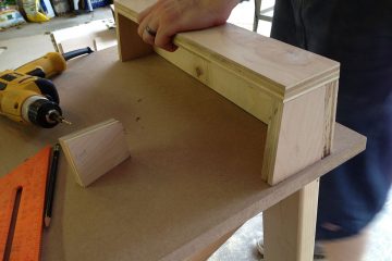
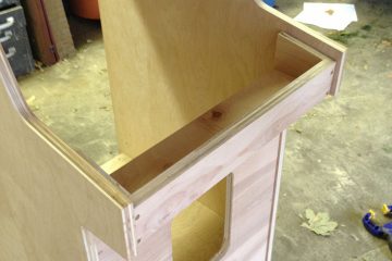
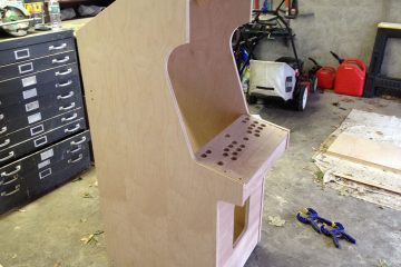
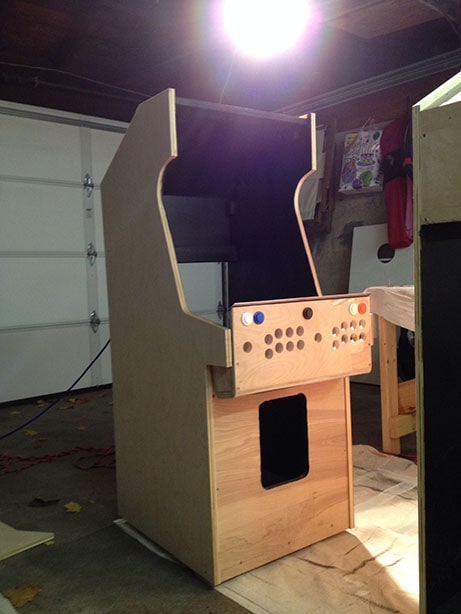
The next phase was probably the most complicated and time consuming. We had the basic cabinet framework in place, but still needed to build out the control panel, monitor mount with bezel, and speaker grill. Most of the time spent here was drawing up plans and measuring.
Control Panel
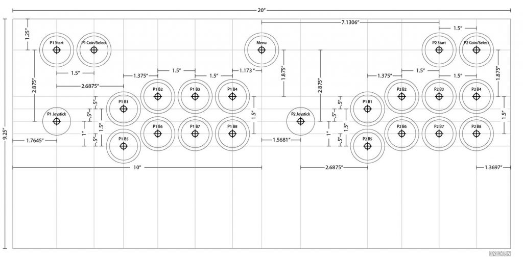
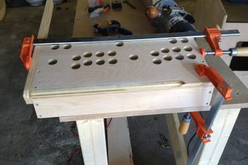
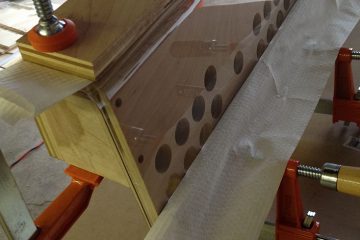
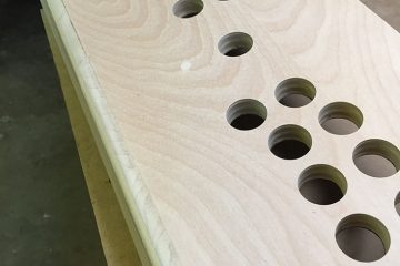
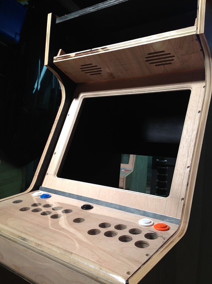
I looked over pretty much every control panel layout I could find on the internet. I figured we could find a template, print it out, and start drilling. With a cabinet width of only 20″, we had to squeeze a lot in and make it as comfortable as possible for 2 players with 8 buttons each. We have to drill a total of 23 holes for buttons and joysticks into a board that is only 9¼” x 20″.
We decided on 8 buttons per player for a few reasons, but mainly because I love Neo Geo and wanted a 4 button row and it will give us more options in the future.
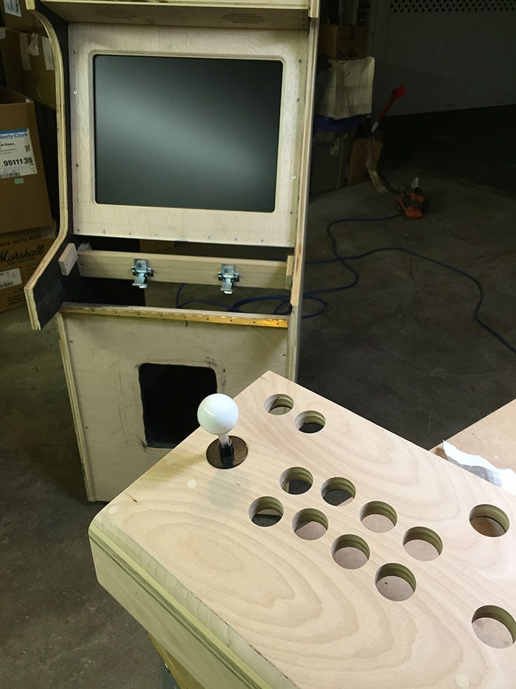
Our buttons required 1⅛” diameter holes. The joystick can work with a smaller diameter hole, but since our panel is ¾” thick we need to use an extended shaft which effects the throw distance. So, for the joystick holes we used the same diameter as the buttons which allows for the extra joystick travel.
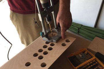
The measurements were drawn on a piece of MDF so a template could be created. A 1⅛” forstner bit was used to drill holes through the plywood using the MDF template as guide. The top and bottom front edges of the control panel were rounded using a ¾” radius bit to remove the hard edges where palms would rest.
In some photos you will see we applied an initial coat of paint. We started painting tight areas early on because we knew once everything was assembled it would be really difficult to reach some parts.
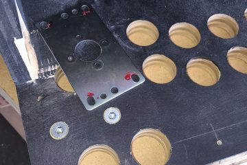
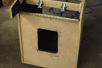
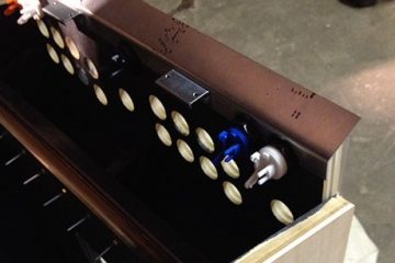
When we started test fitting components on the control panel we realized we didn’t leave enough room for the left joystick. The mounting plate and the micro switch holder were about ⅛” too wide. We had to notch out a section of the side wall to fit it.
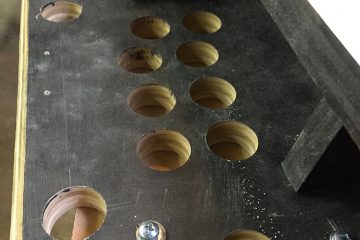
To mount the joysticks we used threaded inserts that were epoxied into the control panel. The lower inserts had to be drilled from the top down. We will fill these holes and the recessed screw holes with wood filler.
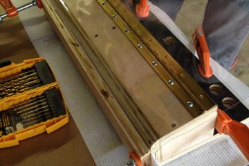
The control panel will also be hinged on the bottom, like a classic arcade machine, to allow access to the wiring. For this we installed 1½” continuous brass hinge cut to size. This will be mounted using truss head machine screws with washers and nuts so it can be removed as needed without destroying the wood.
You can see in the pictures that we also attempted to wrap the control panel with protective plastic. We tested Lexan, acrylic, and a vacuum-forming plastic with clamps and heat guns. This was a giant waste of time so don’t do it. The shiny plastic is ugly and adds thickness to the control panel. Buying the right material for the control panel overlay artwork is the right way to do this.
We’ve added an aluminum bracket that was cut to fit around the push buttons and angled on a bending brake. This will protect the edge of the wood as well as act as retainer for the glass that will sit in front of the monitor. Attached to the aluminum bracket we have added latch clamp brackets where latches mounted to a cross post will hold the control panel down (Control Panel Latch CPLATCH from mikesarcade.com)
Monitor Mount and Bezel
We are going with a 20″ 4:3 LCD monitor (Dell UltraSharp 2007FP). With the exception of some vertical shmup games, the games we’ll be playing are 4:3 ratio. I’m not a fan of 16:9 in MAME cabinets. We’ll be playing classic games and want them to fill the monitor.
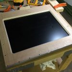
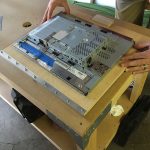
The monitor bezel will be ½” plywood with a beveled edge. We removed the LCD panel from the plastic body and built a makeshift wooden frame to match the dimensions of the LCD panel. The frame was used as a guide for a router with a flush trim bit. Then a 45° bearing bit was used to route a beveled edge.
We created an aluminum L bracket with a ³⁄1₆” lip on the bottom to hold the glass panels. On the center of the lip we cut a round piece out so you could get a finger under the glass to remove it as needed. The bracket screws will be hidden by the control panel edge bracket which also holds the glass in place. We ordered sheets of ³⁄1₆” thick x 19⅞” wide x 17⅞” tall tempered glass with a seamed edge from onedayglass.com and were very happy with them.
On the top of the bezel we added a wooden stop that will prevent the glass from sliding up too far and falling out during transit, but high enough to allow the glass to be lifted up and out of place for cleaning when the control panel is open.
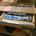
We used the VESA screw holes on the monitor with a cross board to attach the monitor directly to the bezel. This ensures the bezel aligns perfectly with the monitor while still being able to remove the monitor.
Speaker Grill
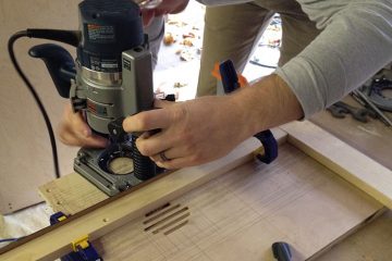
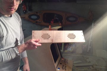
Almost done with cutting wood. The speakers will be mounted behind the marquee and face perpendicular to the monitor. The panel below the marquee is just big enough to fit 4″ speakers. We used a router with a ¼” bit to route slots directly in the plywood panel. This gives a really clean look and doesn’t require a mesh grill cover. We left a ¼” gap between the speaker grill panel and the monitor bezel to leave space for the glass to slide up between them
Paint
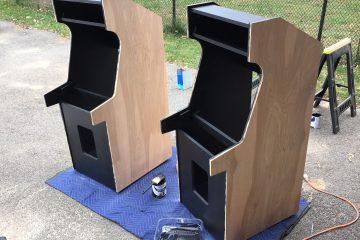
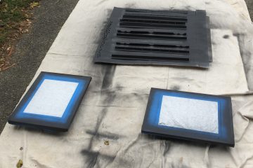
Not much to talk about here. We sprayed all brackets, hinges, bezels, and screws then brushed and rolled the inside and outside panels with matte black paint. The sides will be prepped separately for adhesive-backed vinyl artwork prints.
All we have to do now is wire it up, slap on some artwork, and start playing games…
