Sega ST-V Stereo Audio + CPS2 Kick
This is a project overview of how the Everten ST-V Stereo Audio + Kick PCB came to be. Below is the process I went through to eventually arrive at my first (and second) ever PCB design.
Rough Cut
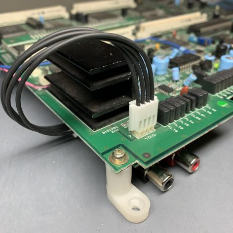
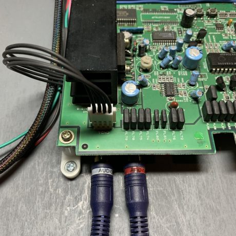
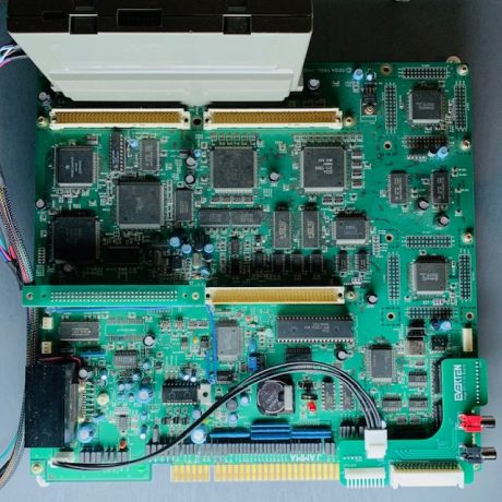
The Sega ST-V outputs mono from the JAMMA edge. However, there is a line-level stereo connector at CN24 via a 4-pin JST NH header. CN24 pin layout 1-left 2-ground 3-right 4-ground.
You can wire this connector directly to RCA jacks, but I wanted to make a more permanent method without wires hanging out everywhere. I started attempting to fabricate a metal panel that could be mounted directly to the ST-V that had panel-mount RCA jacks.
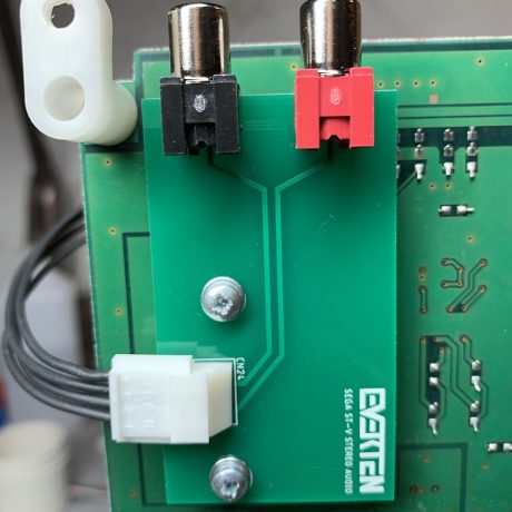
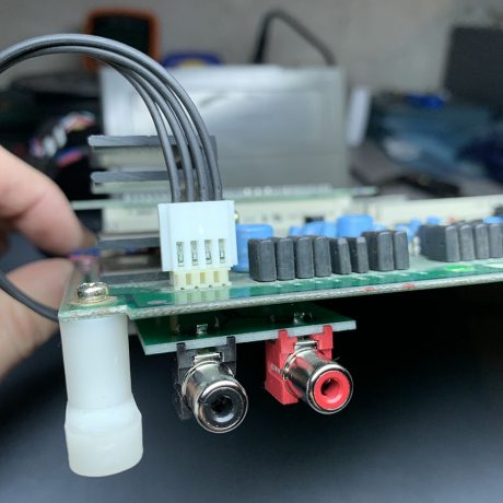
On the under side of the STV board the audio heat sink is mounted with screws to the PCB. This seemed to be a suitable spot to mount a custom panel. After some trial and error I ended up with an aluminum bracket holding the RCA jacks and a wire harness to connect them to the STV. The bracket could be mounted by removing the heat sink screws and used standoffs in their place. The STV board would require PCB feet to raise it up enough to fit the bracket.
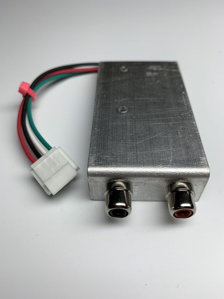
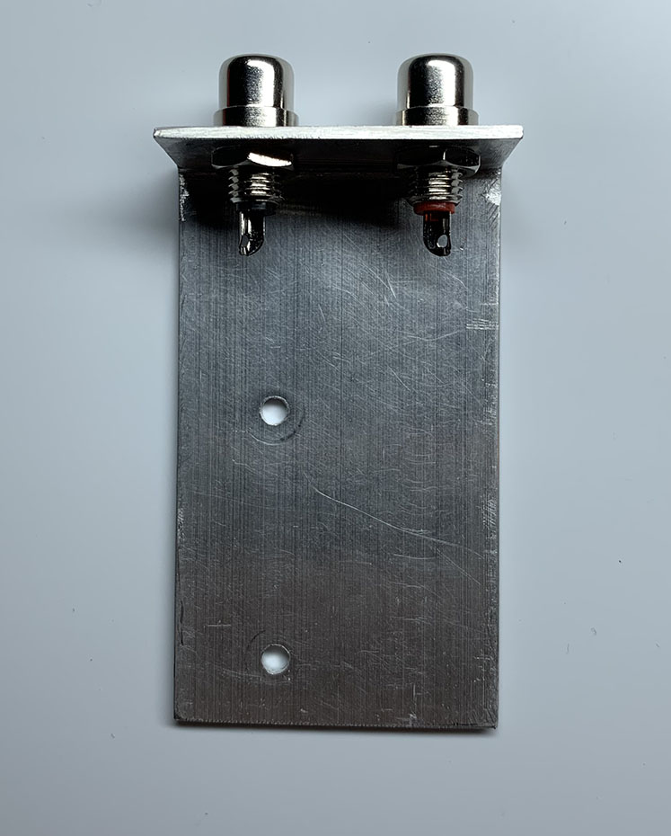
This solution worked, but it wasn’t ideal or easily reproduced. I’m not really setup with the proper tools to for cutting and bending metal with any sort of precision. It also isn’t the most attractive thing to look at.
It dawned on me that this would be the perfect opportunity to learn how to design a really simple PCB and mount it in the same fashion as the bracket. I downloaded the free version of AutoDesk Eagle and started trying to figure it all out. I had to learn how to design parts and footprints as well since I couldn’t find libraries for what I needed.
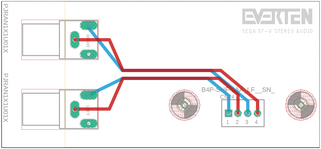
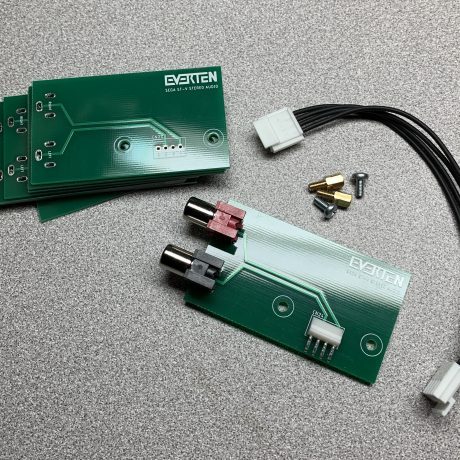
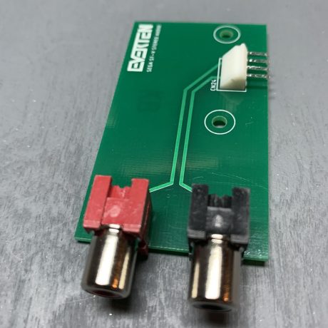
This came to be the Everten Sega ST-V Stereo Audio PCB. I sent the boards to PCBWay for manufacturing and ordered all of the parts for assembly once they arrived.
Parts List:
1 x Left Audio – PJRAN1X1U01X
1 x Right Audio – PJRAN1X1U03X
1 x 4 Pin Header – BS4P-SHF-1AA(LF)(SN)
2 x 4 Pin Receptacle – H4P-SHF-AA
8 x Female Contacts – SHF-001T-0.8BS
4 x 8″ 22GA wires
2 x 5mm Standoffs – Duratool D01494
2 x 6mm M3 Screw – Duratool WASH3
2 x M3 Washer – TR Fastenings M3 6 PRSTMC Z100
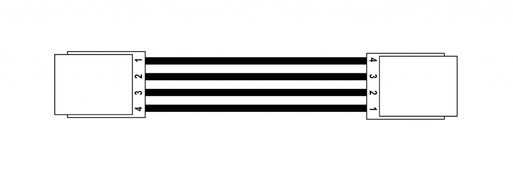
Note: CN24 on my Stereo Audio PCB is reverse-pinned and the wire harness is to be wired as such. The cable harness NH connectors should be wired as pins 1-4, 2-3, 3-2, and 4-1. This is straight wiring as pictured.
Assembled and installed. The board fit well and didn’t need any other tweaks other than a small footprint adjustment on the RCA connectors, but that didn’t have any real impact on functionality.
Improving the Design
There was still more to be done. The ST-V has some games that support a 6-button layout. The JAMMA edge only provides input for a 3 buttons. In order to get the extra 3 buttons you need to connect to CN21 using a CPS1-style kick harness. The more widely used kick harness connector seems to be the CPS2 connector and happens to be the connector I use in my cabinets. I started trying to figure out how to incorporate the CPS2 kick harness into my Stereo Audio PCB.
I wasn’t a huge fan of they way the Stereo Audio PCB mounted under the STV PCB. Some people don’t use PCB feet or they have custom built cases for their boards that might not allow for the board to be mounted in that position. So, the PCB needed a new home on the STV board.
There are several connectors on the front right portion of the STV. One of them is the CN21 kick harness connector for the extra 3 buttons. Some STV’s have an daughter board that plugs down into these connectors. I cannot find a lot of information about this daughter board, but STV’s that have it function normally without it, so it is assumed it is some sort of pass through. This plug-in method seemed like a good way to mount a new style audio + kick harness PCB.
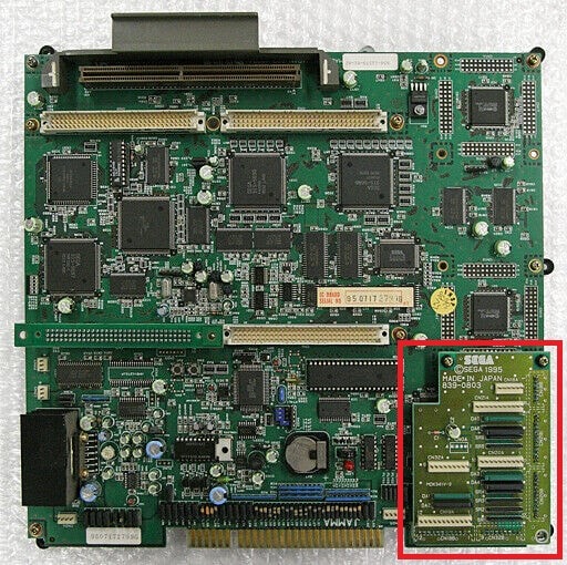
The matching female board-to-board connector for CN21 and the other adjacent connectors are the JST HVQ series. The last I checked these were only available directly from JST in Japan and needed to be ordered in quantities of 500 units. It didn’t seem practical to order in those quantities. After a lot of searching I settled on the Molex KK 254 series connectors instead which are readily available. These have a slightly smaller pin pitch, but fit ok up to the 11 pins needed for the CN21 connector.
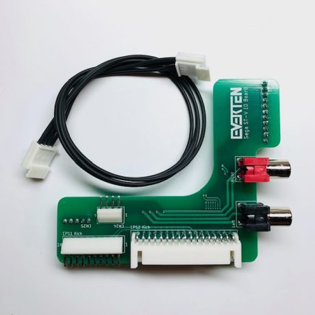
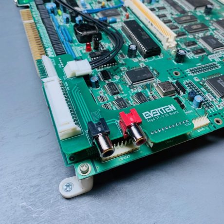
The idea was to design the new board to be a drop-in install without mods, screws, or soldering to the STV main board. I decided to use a second connector on the STV board (CN25) as a mounting point along with the CN21 connector. Having the new board plug down into the CN21 connector meant there was no need for a second wire harness as the kick harness connections would already be on the PCB. All I would need is a longer 4-wire harness for the audio.
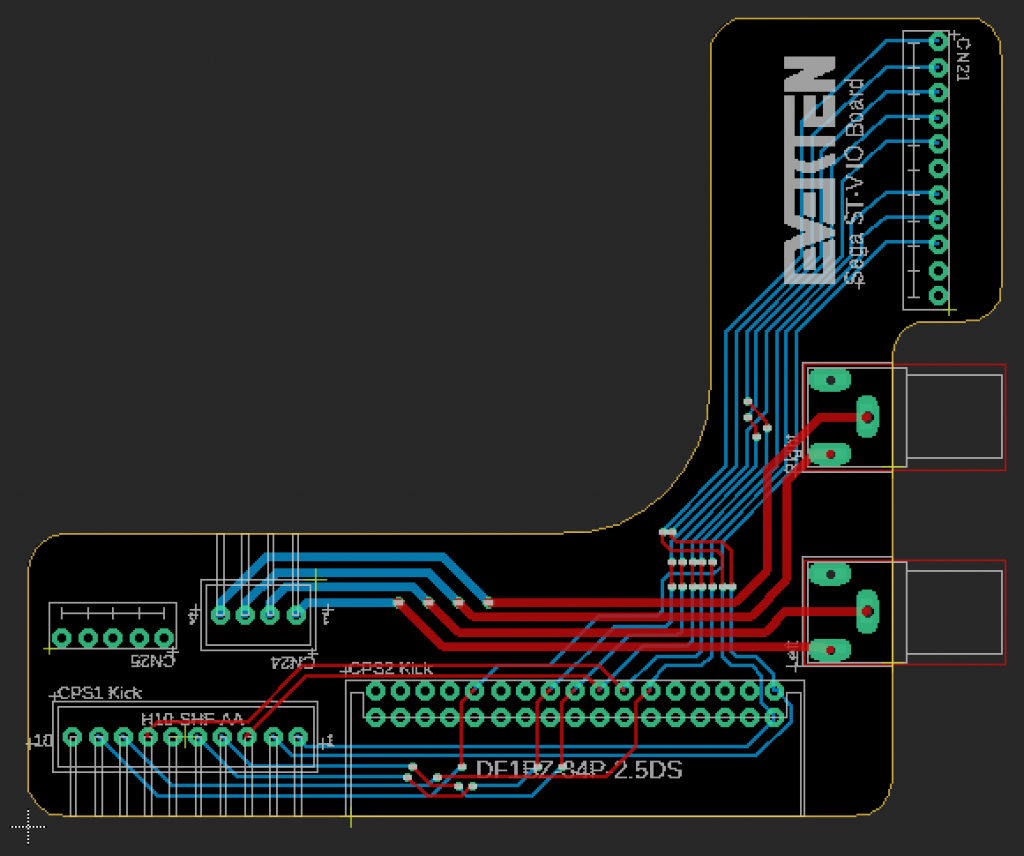
I left the board footprint as minimal as possible because the only support it had were the two Molex connectors. I inset the RCA jacks to keep them flush with the right edge of the STV main board to keep it looking clean. The CPS2 connector faces forward to the right of the JAMMA connector. I even had room to add the CPS1 kick harness connector next to the CPS2 connector. I also accounted for the space needed for standoffs for acrylic cases such as the Lions 3 STV Case to make sure it was compatible for everyone’s setup.
The board worked great and fit perfectly on my STV board.
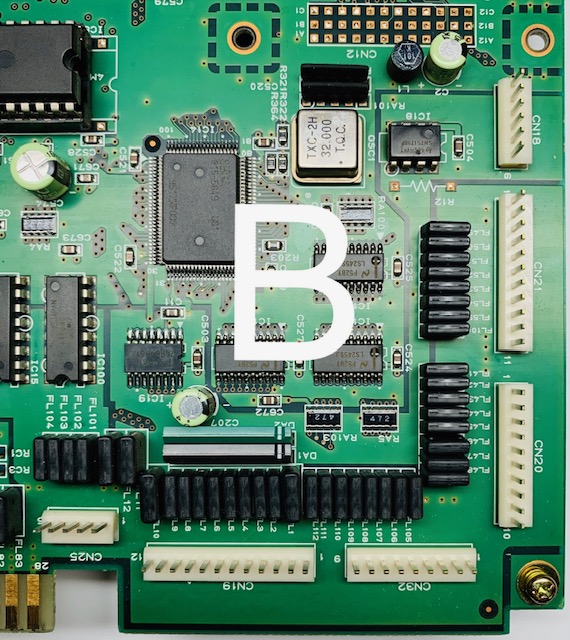
After selling a few of the boards I began receiving feedback that it didn’t fit correctly on some STV boards. I realized there were actually two variations of the STV after seeing some photos from buyers. Boards that shipped with the daughter board had the connectors in the front right of the board slightly shifted. I began referring to the different revisions as A and B layouts. My original design was based on the A layout.
The CN25 I was using as a mounting point was shifted a few millimeters in relation to the CN21 connector causing a misalignment with layout B boards. I quickly created a new CN25 footprint in Eagle that could act as a hybrid connector to accommodate both layouts.
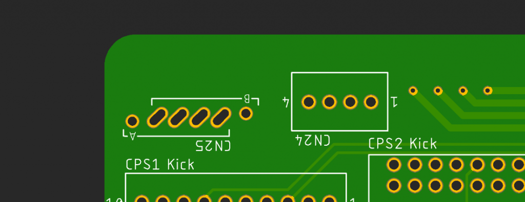
The new hole layout has diagonal slots so the 5-pin Molex connector can be shift one hole left or right and slide up and down slightly. This means I can use the same PCB design for both layouts and simply solder the CN25 connector in the A or B positions. Since I am not passing signal on this connector the pin position doesn’t matter.
The wire harness remains reverse pinned as with the Stereo Audio PCB.
Parts List:
2 x H4P-SHF-AA – wire connector housing
4 x 13″ 22GA wires
8 x SHF-001T-0.8BS – wire crimp connectors
1 x BS10P-SHF-1AA(LF)(SN) – CPS1
1 x Molex 22022055 – CN25
1 x Molex 22022115 – CN21
1 x PJRAN1X1U01X – Left RCA
1 x PJRAN1X1U03X – Right RCA
1 x BS4P-SHF-1AA(LF)(SN) – CN24
1 x DF1BZ-34DP-2.5DS – CPS2
I’ve tweaked the screen print layers over time so there are a few different revisions of this PCB in the wild. However, the overall design and part positions have remained the same.
The ST-V Stereo Audio PCB and the ST-V IO Board are available on the Arcade Projects forums and this website.
Check out the video overview from Scarlet Sprites on YouTube below as well as the small write up on RetroRGB.com about the PCB.
